Load case combinations have been a part of the building codes and The American Society of Civil Engineers (ASCE) 7 for some time now. In the 2007 rewrite of ASME Section VIII, Division 2, we saw the introduction of load case combinations into the new version of that code. Word on the street is that UG-22 in ASME Section VIII, Division 1 will have load case combinations specified in a future edition, even as soon as the 2025 publication. Additionally, load case combinations are prevalent in third-party and industry standard specifications like JIP33, MODEC or those required by Engineering, Procurement and Construction companies (EPCs).
The following blog aims to further prepare those in the industry affected by these new code updates and provide guidance on how to successfully consider those combinations for wind and seismic loads.
What is a load case combination?
Load case combinations take different types of loads (seismic, dead load, wind, and so on) in combination with each other, and then compare the combination to some sort of acceptance criteria. In these combinations, the different types of loads have some sort of multiplier on them. For example:
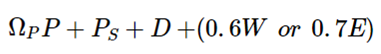
ASME Section VIII, Division 2, Table 4.1.2 Combination 5
![]()
P is the design pressure (internal or external) and omegaP is 1 unless otherwise specified by the end user. Ps is the static head, D is the dead load (or transport load), W is wind and E is the seismic/earthquake value.
To simplify, the case would look at the combined effect of pressures, a 100% of the weight and either 60% of the wind load or 70% of the seismic load, whichever is worse.
ASCE 7-22, Strength Design 2.3.5, Combination 7 Without Overstrength
![]()
D is the dead load, Ev is the vertical seismic and Eh is the horizontal or lateral seismic.
This combination looks at 90% of the weight in combination with the 100% of the vertical seismic load acting upward (Ev is defined as acting downward, so the – reverses that), and 100% of the horizontal or lateral seismic load. The load case does not explicitly specify what to do about pressure.
International Building Code (IBC) 2021, Alternative Allowable Stress Design Combinations 1605.2, Equation 16-3
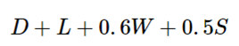
D is the dead load, L is the live load, W is the wind load and S is the snow load.
This combination looks at 100% of the weight, 100% of the live load, 60% of the wind load and 50% of the snow load. The load case does not explicitly specify what to do about pressure.
What load case combinations must be satisfied for the equipment I am purchasing or fabricating?
To answer that, a series of questions should be considered.
Does the vessel have a Division 2 stamp on it?
If the answer is yes and Part 4 is used for the design (Design By Rule), then the combinations in Table 4.1.2 must be satisfied.
Does the location of installation require compliance with certain building codes?
If the answer is yes, then combinations from IBC, CBC or ASCE 7 may need to be satisfied.
Does the end user have their own specs? Or is an EPC involved and requires their own spec? Is there an industry spec that is required?
If the answer is yes, then these additional combinations must be satisfied.
Additionally, other engineering decisions should be considered for load case combinations, like:
- Is the dead load based on the flooded weight, empty weight or operating weight?
- Do I need to use the overstrength factor?
- Do I need to check the unpressurized case?
- In ASCE 7, do I use Strength Design or Allowable Stress Design?
In considering all of these questions, engineers usually run a bunch of load case combinations to satisfy requirements. But, it has to be easier than that, right? It SHOULD be easier than that. First, let's look at why these calculations are run.
So, it seems like I need to run calculations on a bunch of different load case combinations, but why?
Let’s look at a couple of facts. Seismic loads are based on weight, and when the weight goes up, the magnitude of the seismic load goes up. Wind loads are based on projected area, and as the projected area goes up, the magnitude of the wind load goes up. With that understanding, let's consider the following load case combinations from ASME Section VIII, Division 2 as mentioned above:
Or, it could be that the highest tensile stress case on the bottom shell course is the sub-combination (internal pressure, empty, wind), with a static head set to zero because the vessel is empty:
![]()
Or it could be that the highest compressive stress case on the skirt is the sub-combination (external pressure, flooded, seismic horizontal and vertical downward action), with a static head set to zero to be conservative in combination with external pressure:
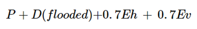
Basically, the equipment has multiple components that may fail under different loading combinations and each prescribed load case likely implies several permutations within itself.
How can I better consider these combinations with ease?
Pressure Vessel software exists today that not only provides code assistance for design compliance but also helps guide engineers through updates like these that can halt design and overall production.
DesignCalcs, CEI’s leading pressure vessel design software, built to provide engineers with ASME Section VIII code assistance, supports the determination of lateral or vertical wind loads and lateral seismic loads for several building codes and ASCE 7.
Watch the Video to Learn More
The software defaults the multipliers on these loads based on the Allowable Stress Design (ASD) Basic Combinations (that include wind and seismic). In addition, it allows further permutations of these combinations by allowing these to be checked based on operating liquid levels, empty, pressurized (internal and external) and unpressurized factors. DesignCalcs, also considers the overstrength factor, but by default, and it only affects the resulting loads on the structural support elements in contact with the foundation.
Since this is an ASD basis by default, the allowable stresses are not increased during the application of the wind and seismic loads. These are just the default settings.
In order to accommodate different codes, multiple end user specifications, different interpretations of how to treat the overstrength factor, or even strength design combinations, DesignCalcs allows for the customizations of these different multipliers. If instead you prefer to calculate the resulting seismic multiplier on weight directly, or the wind pressure at a certain elevation, you can do that as well. The user can also override the default to increase the allowable for cases with wind and seismic.
Why Considering DesignCalcs Saves You Time & Money
So if you're worried about the load case combinations updates to the code or about third-party specs while designing your pressure equipment, considering pressure vessel software with code assistance can help you save time, money and headaches.
Schedule a Discovery Call Today to talk to a representative. And, if you're looking for online training to better understand code-assistance software from the experts who design it, consider using a CEI product in conjunction with the ThinkTank Academy.

Leave a Comment