
- Determine the Chemical Composition and Tensile Strength of the Base Metal
- Narrow Filler Metals Options Relative by Welding Process
- Account for Welding Position
- Read the Welding Electrode Designation Format
Getting this wrong has real consequences under any welding code, including ASME Section IX (Boiler and Pressure Vessel Code), AWS D1.1 (Structural Code), and API 1104 (Pipeline Code).
A mismatch between base and filler metal can reduce overall tensile strength, lower load-bearing capacity, and in the worst case, lead to catastrophic failure.
Four steps will help you match the filler metal to the base metal accurately:
Step 1. Determine Chemical Composition and Tensile Strength of the Base Metal
When matching filler metal to base metal, the filler metal must be compatible with the base metal's chemical composition and tensile strength. Use this information to match chemical properties and determine the strength of the structure being welded.
For example, welding base metals with a tensile strength of 60,000 psi requires electrodes of the same or greater tensile strength to maintain the strength of the base metal. E6010 or E7018 would both work in that scenario. Whether it's a pressure-containing vessel or a load-bearing structure, tensile strength tells you the resistance at which a material will break under tension.
Start here before you consider anything else.

Step 2. Narrow Your Filler Metal Options by Welding Process
Knowing which welding process will be used dramatically reduces the number of filler metal options you need to evaluate. The AWS Filler Metal Specifications chart groups filler metals with similar chemical properties into the same specification and assigns each an A/SFA Number.
AWS also charts these specifications by material and welding process, as shown in the table below. This shows how quickly the list of possible filler metals narrows once you know your process and material.
AWS Filler Metal Specifications by Material and Welding Process |
| OFW | SMAW | GTAW GMAW PAW | FCAW | SAW | ESW | EGW | Brazing | |
| Carbon Steel | A5.2 | A5.1 | A5.18, A5.36 | A5.36 | A5.17 | A5.25 | A5.26 | A5.8, A5.31 |
| Low-Alloy Steel | A5.2 | A5.5 | A5.28, A5.36 | A5.36 | A5.23 | A5.25 | A5.26 | A5.8, A5.31 |
| Stainless Steel | A5.4 | A5.9, A5.22 | A5.22 | A5.9 | A5.9 | A5.9 | A5.8, A5.31 | |
| Cast Iron | A5.15 | A5.15 | A5.15 | A5.15 | A5.8, A5.31 | |||
| Nickel Alloys | A5.11 | A5.14 | A5.34 | A5.14 | A5.14 | A5.8, A5.31 | ||
| Aluminum Alloys | A5.3 | A5.10 | A5.8, A5.31 | |||||
| Copper Alloys | A5.6 | A5.7 | A5.8, A5.31 | |||||
| Titanium Alloys | A5.16 | A5.8, A5.31 | ||||||
| Zirconium Alloys | A5.24 | A5.8, A5.31 | ||||||
| Magnesium Alloys | A5.19 | A5.8, A5.31 | ||||||
| Tungsten Electrodes | A5.12 | |||||||
| Brazing Alloys and Fluxes | A5.8, A5.31 | |||||||
| Surfacing Alloys | A5.21 | A5.13 | A5.21 | A5.21 | A5.21 | |||
| Consumable Inserts | A5.30 | |||||||
| Shielding Gases | A5.32 | A5.32 | A5.32 |

Step 3. Account for Welding Position
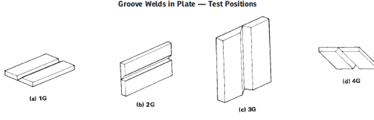
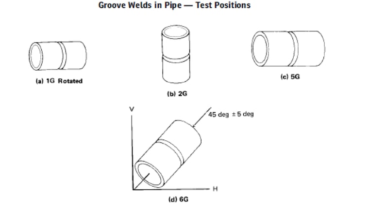
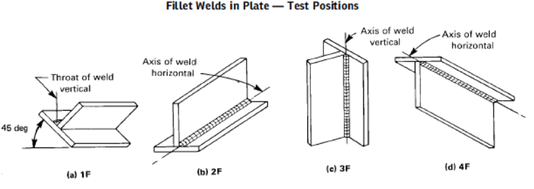
Welding position is another critical variable when selecting the right filler metal. Some filler materials are so fluid when molten that using them in vertical or overhead positions can endanger the welder and prevent complete joint penetration. The electrode designation (Step 4) tells you which positions a given filler metal can handle.
Groove Welds
Below are example welding positions for groove welds (plate and pipes) and also fillet welds (plate) positions.
Step 4. How to Read the Welding Electrode Designation
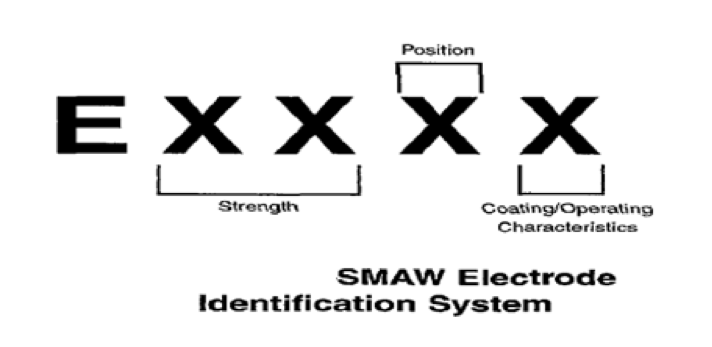
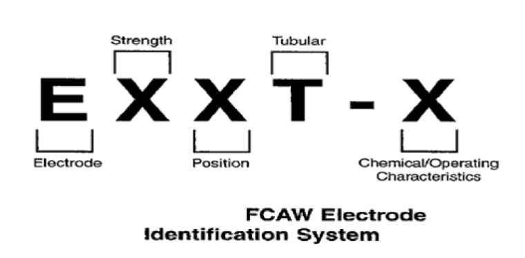
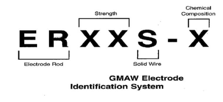
The final step, and arguably the most critical, is knowing how to read the electrode designation. The identification value consists of an "E" (for electrode) followed by four to five digits.
Tensile strength: The first two or three digits indicate the minimum tensile strength of the filler metal. For example, E7018 tells you the electrode has a minimum tensile strength of 70,000 psi from the first three characters "E70".
Position: The next digit represents the position in which the electrode can be used.
- A value of "1" means the electrode is suitable for all positions.
- A value of "2" means the filler metal is so fluid when molten that it can only be used in the flat position for all weld types and the horizontal position for fillet welds.
- A value of "4" means the electrode is suitable for welding in a downhill progression.
Chemistry and operating characteristics: The final digit indicates the chemical and operating characteristics of the filler metal material. Its meaning depends on the welding process. Below are examples of the electrode identification system for three welding processes: SMAW, FCAW, and GMAW.
Welding Electrode Identification
Matching filler metals to base metals is one of the most important factors in welding. Understanding these four steps increases safety during fabrication and over the full service life of whatever you're building.
ProWrite supports filler metal and base metal matching using P-Numbers, F-Numbers, A-Numbers, and SFA specifications, with access to thousands of built-in material records and code-assisted compliance checks for ASME Section IX, AWS D1.1, and API 1104. If you're documenting welding procedures, it handles the lookups so you don't have to cross-reference manually.
Want to see how ProWrite handles filler metal matching for your code? Then check out ProWrite, a welding documentation software that will help with this step and many more of your welding needs.




Leave a Comment