The need to perform finite element analysis (FEA) has become more and more prevalent in several industries. A variety of pressure vessel and piping design problems that engineers often face stem from traditional and outdated design methods, that often, cannot check all the boxes when designing for compliance and cost-effectiveness.
These FEA methods are perhaps even more critical for evaluating existing equipment for safety than using them to design new equipment altogether. In the pressure equipment industry, a fitness-for-service (FFS) evaluation is critical because it prevents the cost of an entire replacement vessel or pipe as well as factory shutdowns.
In this article, you will read about the methods used within FEA, FEA itself, and how consideration of both linear and nonlinear options can prevent costly time and resources.
What Is Finite Element Method (FEM)?
FEM is the most powerful and effective numerical technique used to perform FEA, which has advantages over most other numerical analysis methods. For instance, FEM can:
- Be applied to any issue related to a field like heat transfer, structural analysis, fluid field, electromagnetic field and so on.
- Contains no geometric restrictions, so it’s capable of handling geometrically complicated shapes.
- Has no limitations on boundary conditions and loading.
- Has no restrictions on material properties.
- Can accommodate different types of elements like brick, shell, beam, contact, axisymmetric, and more.
- Accounts for an improved finite element approximation by refining the mesh or increasing the element order [1].
What Is Linear FEA?
As for structural analysis, linear elastic analysis is the most common type of FEA. To utilize linear FEA, the structure must satisfy the following circumstances:
- The material has elastic behavior, which means there is a linear relationship between the stresses and strains.
- The strains are infinitesimally small and the structural deformation has no impact on the behavior of the structure.
The Pros and Cons of Linear FEA
In terms of advantages, linear FEA can provide engineers with:
- Simple analyses that can be carried out faster with no need for costly load incrementation or iteration schemes.
- Solutions for different load cases that can be superimposed and the number of material constants required can be reduced to a minimum.
In terms of disadvantages, the following drawbacks can exist when using linear FEA:
- Debate for What's Standard: Stress categorization per ASME Section VIII, Div 2 and similar codes can cause debate between engineers and reviewers. ASME provides guidelines for the classification of linear elastic stresses into primary, secondary, and peak stresses. In the case of complex geometries and complex load cases, there are different kinds of stresses, which have different degrees of significance, so engineers may disagree on how to categorize those stresses.
- Getting the Whole Picture: Ignoring non-linear behavior may lead to overly conservative designs.
In many instances, linear analysis provides a reasonable idealization of structural response. However, some circumstances exist where nonlinear effects must be incorporated for a realistic assessment of structural deformation, which requires nonlinear FEA.
What Is Nonlinear FEA?
Two common types of nonlinearities exist in the field today--geometric nonlinearity and material nonlinearity. To see the two types of nonlinearities illustrated further, refer to the Appendix section of this article.
In the case of geometric nonlinearity, the displacement is large, which results in a nonlinear strain-displacement relationship. As a result, this makes the structure become stiff and prompts the change of the load direction as the deformation starts to occur.
Material nonlinearity means that the stresses are not linearly proportional to the strains. For instance, when metal material becomes plastic, the stress-strain curve becomes nonlinear.
But, it's important to note that several increased complexities exist when considering nonlinearity [2]:
- The superposition principle does not hold any more.
- The final deformation can be loading path dependent. For instance, the nonlinear behavior of a pressure vessel that is first heated and then pressurized is quite different if the loading sequence is reversed.
- The initial stress state in a structure (welding residual stresses) is important to consider.
- The response of a structure can be significantly non-proportional to the applied loads.
While it's important to note those drawbacks, nonlinear analysis is often required when engineers encounter the following problems (this list is not exhaustive):
- Thick-walled pressure vessels.
- Limit load analysis or elastic-plastic stress analysis as specified by ASME Section VIII, Div 2.
- The assessment of existing structures whose structural integrity might be in question due to damage, aging, corrosion or special loadings not envisioned at the design stage, which is especially true for Fitness-for-Service (FFS).
- The investigation regarding the causes of structural failure.
- Numerical simulation of metal forming.
Fig 1. Pressure and External Load Run Results from Performing an Elastic Plastic Analysis in FEPipe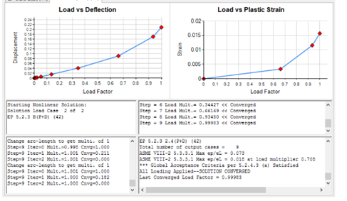
How the PVPT Design Suite Can Help
NozzlePRO and FEPipe are FEA software modules specifically tailored for pressure vessel and piping design. These industry-leading FEA solutions allow you to:
- Design and validate your own complex pressure equipment for safety or import designs you’ve already created.
- Perform a level three fitness-for-service (FFS) assessment, which include local thinning and crack analysis.
- Access and manage inspection data and easy-to-read automatic ASME stress reports.
Fig 2. Nozzle Displacement Results from Performing a Nonlinear Analysis in FEPipe.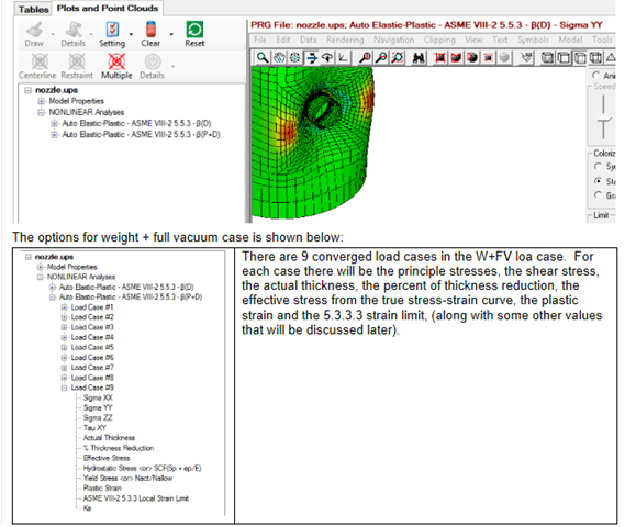
Since both NozzlePRO and FEPipe are modules within the PVPT Design Suite, they have native integrations with CEI's DesignCalcs and Finglow modules. Thus, bringing an extra level of code compliance capabilities to designs. With this integration, customers can easily and quickly check nozzles, saddles, pipe shoes and clips as well as shell and brick models against ASME Section VIII, Div. 2, Part 5 and other codes.
With elastic-plastic/non-linear FEA solvers, NozzlePRO and FEPipe determine stresses and deformations predicted by real-world examples–meaning they help you determine compliant, yet cost-effective geometries and materials needed for your design and validation requirements.

So, if you’re looking for an easy way to perform FEA without having extensive knowledge or time to do so, schedule a discovery call with us today to see how our products can fit your PVPT design needs.
Appendix
Geometric Nonlinearity
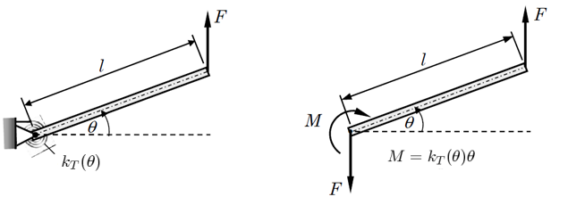
Let’s assume a rigid link supported by a linear elastic torsional spring at one end subjects to a vertical point load at the other end, as shown in the following figure [3]:
Fig. 1 Rigid Link-linear Torsional Spring Cantilever
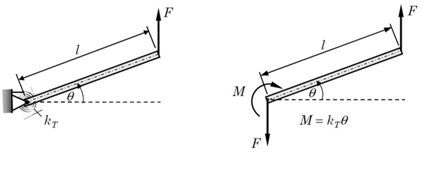
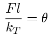
In which case, an equilibrium of the moment with respect to the hinge gives
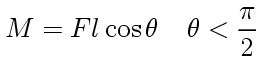
And the linear moment-rotation relationship from the torsional spring satisfies,
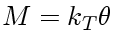
By combining both, we have
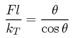
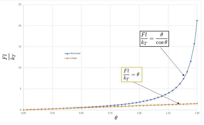
So, the relationship between the force and rotation angle is nonlinear. If the rotation angle is small (less than 10 degrees), the following holds,
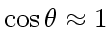
As a result, we have linear relationship between the force and rotation angle as follows,
From the figure below, it is clear that the nonlinearity is due to the large values of the rotation angle, namely, due to the geometry of motion. For the small angle, the response is linear. It should be noted that for the same magnitude of force, the deflection in a nonlinear case is less than that in a linear case.
Fig. 2 Geometric Linear and Nonlinear Response of a Rigid Link-linear Torsional Spring Cantilever
Material Nonlinearity
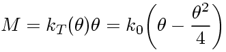
Looking at the same example from the section above, if the stiffness of the torsional spring is not a constant and instead it is a function of the rotation angle, we can assume the torsional stiffness is related to the rotation of the angle.
Fig. 3 Rigid Link-linear Torsional Spring Cantilever
And the relationship in terms of function takes the following form:
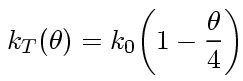
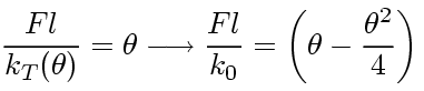
Then, the moment-rotation relationship becomes nonlinear as described here:
If we neglect geometric nonlinearity, namely, the cosine term, the following will hold:
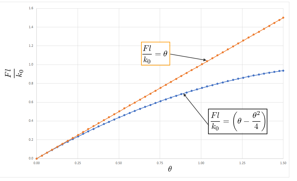
As shown in the graph below, the comparison is illustrated between the case where the torsional stiffness is a constant and where the torsional stiffness is a function of the rotation angle.
Fig 3. Material Linear and Nonlinear Response of a Rigid Link-linear Torsional Spring Cantilever
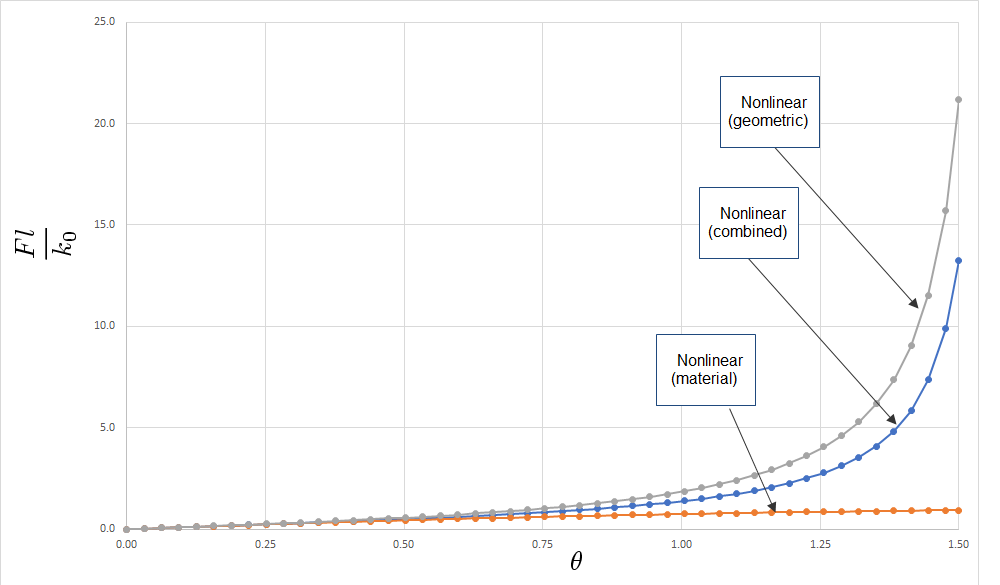
In essence, material nonlinearity and geometric nonlinearity can happen at the same time. In this case, the relationship between force and rotation angle is:
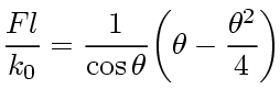
The following graph describes the response of the cantilever with respect to the different types of nonlinearities under consideration:
Fig 4. Response of Cantilever Against Varying Nonlinearities
References
[1] R. D. Cook, Concepts and Applications of Finite Element Analysis, (Wiley, New York, 2002)
[2] E. Hinton, Introduction to Nonlinear Finite Element Analysis, (NAFEMS Ltd, 1992)
[3] J. N. Reddy, An Introduction to Nonlinear Finite Element Analysis, (Oxford University Press, 2015)

Leave a Comment