If there's one thing Robert Weyer (Lead Piping Engineer for Amesk) knows, it's how to implement modern methods of piping design and construction to account for those requirements where the only guidance in B31.3 is that codes “shall be taken into account.”
As a piping and mechanical engineer based in Perth, Australia, Robert has made several contributions to improve old methods of design and analysis by taking advantage of new methods made available by modern piping software to solve today’s most prevalent piping challenges.Throughout his career, and more recently through his involvement with recent LNG projects in Australia, Robert realized that many piping design and construction methods with widespread industry use dated back decades before, often to the 1940s and 1950s. Despite being well into the 21st century, he found that the industry was not taking full advantage of the advances in computer software and hardware advances available to engineers today. These not only expedite the design process but allow engineers to better address compliance issues than traditional methods [R. Weyer, personal communication, 8 August 2022].
In 2018, he co-authored a conference paper about better assessment and management of the risks inherent in pneumatic testing for the ASME Pressure Vessel and Piping (PVP) Conference in the Czech Republic [1].
The paper recommended methods to improve the management of fragment throw risk, which was historically ignored by the industry codes despite having resulted in fatal accidents following explosions during pneumatic testing. Basically, while codes play a crucial aspect in ensuring safety, they cannot be expected to provide guidance on every potential hazard a piping system could be exposed to. If a pneumatic test goes wrong, there can be disastrous consequences if the exclusion zones do not allow for both blast wave and fragment throw. These consequences can include injuries, fatalities, site shutdowns and property damage [1].
Since then, Robert has published paper after paper. His latest paper about performing more accurate pipe stress analysis with shell modeling was presented at the ASME PVP Conference in Las Vegas, Nevada this past July (2022) [4].
Aside from knowledge on a wide range of piping-related issues (modeling piping systems, piping flexibility assessment, testing, code interpretations, common code pitfalls and important matters on which codes are silent) his company, Amesk, specializes in stress analysis of piping systems. Amesk is a license holder for Paulin Research Group's FEPipe and NozzlePRO software solutions for piping and nozzle designs. This can be used for performing both traditional beam-type analyses as well as more advanced shell-type modeling for these cases when beam modeling may give inadequate results. Additionally, several of PRG's on-staff engineers are active in industry design code committees and are aware of important upcoming code changes before they are published. So, PRG software is designed to stay up-to-date as possible and provides users with software that incorporates code changes often before anyone else.
Outdated ASME Methods Cause Today's Most Prevalent Problems
LNG Considerations
The northern coast of Western Australia is blessed with an abundance of natural gas, but the long distance from the end customers (for example in Korea and Japan), means that the gas needs to be liquefied for transport. Over the past decade, Chevron has built two large Liquified Natural Gas (LNG) plants to turn natural gas into liquid: Gorgon on Barrow Island and Wheatstone on the mainland near the town of Onslow. The processing facilities that have been built include inlet facilities from the feed pipeline, an LNG plant, condensate handling facilities, and associated utilities for storage and export of the LNG and condensate.
Aside from LNG, both Wheatstone and Gorgon supply natural gas for the domestic market in Western Australia and tie into the Dampier to Bunbury Natural Gas Pipeline (DBGNP) [5]. The natural gas from Barrow Island is first transported through a 44-mile sub-sea pipeline to the mainland before tying into the DBNGP.
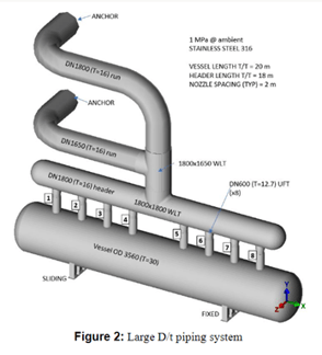
While the B31.3 piping code has its basis in petroleum refinery piping, the piping on LNG plants often poses different challenges regarding refineries. In general, refinery piping has low pressure, high temperature, liquid flows and is predominantly carbon steel. On the other hand, LNG plant piping often has high design pressures, cryogenic temperatures, gas flows and makes significant use of austenitic stainless steel [2]. LNG plants often have very large diameter pipes (DN1800 and bigger) with large D/t ratios (over 100 which is where the code draws the line for Stress Intensification Factors or SIFs).
LNG plants make significant use of stainless steel piping, as the fluids in the pipes are often below the safe temperature range of carbon steel piping. In order to ensure the material remains ductile at low temperatures, stainless steel is used. Due to the higher material cost of stainless steel, piping at larger sizes (DN400 and bigger) is often ordered to the exact specific (as opposed to nominal) thicknesses, which removes that margin of safety that normally exists between the minimum required design thickness and nominal thickness [2].
The high-pressure gas and high flow rates can also cause piping vibration, which the B31.3 code does not address, but merely requires that it “shall be taken into account.” The two-phase nature of the flows can also lead to very high fluid momentum loads for which the code does not provide specific guidance other than the same token of advice--“shall be taken into account.”
While working on various LNG plants in Australia, Robert found that piping design methods and processes based on refinery piping can be unsuitable when dealing with some of the different challenges posed by LNG plant piping. Methods can often be outdated and not take advantage of some of the better methods that modern piping software can offer.
Modern engineering software, such as the software modules in Paulin Research Group's Pressure Equipment Design Suite, can assist in addressing many of these design challenges through the use of finite element analysis (FEA). For maintaining existing plants, fitness-for-service (FFS) can assist in confirming a safe continued operation of piping and avoiding unnecessary costs that go with shutting down equipment.
ASME PVP Conference Published Findings
Over the last several years, Robert has published a variety of conference papers to help address some of the new questions posed to the piping industry. Ultimately, he hopes to contribute to improving the methods used in design while assessing piping systems for mechanical integrity and safe operation. A key theme in all of his papers has been on providing real-world examples of how things can be done better.
2018 Research
As mentioned previously, the 2018 paper focused on managing the risks posed by the stored energy when performing pneumatic testing of piping [1]. One of the key findings was that the quantity of stored energy alone could be a poor indicator of risk and that some very high stored energy tests could be relatively low risk, such as the example presented of two 1.4 km long DN750 stainless steel 304L jetty lines with a total stored energy of 6,675 MJ. Furthermore, fragment throw can pose a greater risk than that of a blast wave. Ignoring the risk of fragment throw (as historically done by codes) can have fatal consequences. This was illustrated by an explosion during pneumatic testing in 2009 at the Deep-Water Port construction site in Shanghai, which resulted in 1 fatality and 15 injuries. This unfortunate incident indicated that while the requirements for exclusion zones (prior to the 2015 edition of ASME PCC-2) protected workers from blast wave propagation, they did not guard against fragment throw.
Robert found that codes and standards addressing pneumatic testing (such as ASME PCC-2 and Australian Standard AS 3788) cannot consider all the risk factors pertaining to a specific pneumatic test. A thorough understanding of the underlying scientific principles behind the code requirements can help engineers reduce the risks associated with pneumatic testing.
2020 Research
In Robert's paper from the ASME PVP 2020 conference, he looked specifically at LNG Plant piping [2]. The paper discussed the challenges posed by LNG piping and how the codes and standards pertaining to piping have been influenced and ultimately improved by the recent boom in LNG plant design and construction.
Specifically, he noted that ASME B31.3 has foundations in refinery piping, which is typically low pressure, high temperature, liquid flows and is carbon steel [2]. As mentioned above, the LNG plant piping often needs to be assessed for loads that are not accounted for in the B31.3 codes. When combined with the fact that the large stainless steel lines are often ordered to exact (as opposed to nominal thicknesses), additional pressure is placed on engineers to ensure the margin for error is reduced.
2021 and 2022 Research
In 2021 and 2022, Robert did extensive work on using shell modeling to analyze piping systems that would usually have been analyzed using beam elements [3], [4].
In a particular case, he researched very high fluid momentum loads on piping and the applicability of the B31.3 allowable stress for occasional loads when assessing piping for a load where it only needs to survive once. This was the focus of his ASME PVP 2021 paper. The paper also discussed other practical considerations for assessing slug loads and presented an improved method using unit vectors to obtain the direction of slug loads on bends.
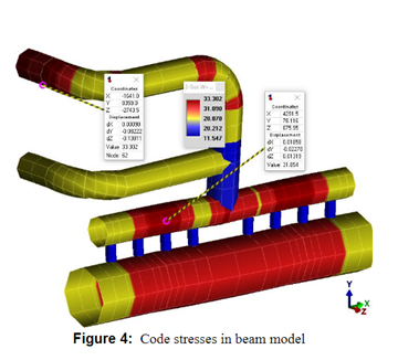
This past July (2022), Robert presented his paper on shell modeling at the ASME PVP Conference in Las Vegas. He noted that a shell model is a better representation of a piping system than a beam model and that it can offer benefits that a beam model cannot. Analyzing piping using shell elements and modern FEA software, like FEPipe, can help engineers better assess piping systems as it provides a better model of the piping. Furthermore, the use of non-linear analysis provides more insight into the behavior of piping material when exposed to loads resulting in stresses that exceed the yield stress.
The Reality of Modern Piping and ASME B31.3
Robert's papers have shown that no code can be expected to address every single design load case that a piping system can be exposed to. In cases where a code is silent on a particular issue, then guidance can be sought from a different code that does address the issue. An understanding of the basis and background of design code can also provide insight into which failure modes the code was attempting to avoid.
In his more recent papers, Robert posits that determining allowable limits isn't always easy for engineers and that often a compromise must be navigated between two competing requirements.
A good example of this is the requirement for adequate flexibility in piping systems–essentially ensuring that when a system expands or contracts due to a change in temperature, the resulting stresses are not excessive. Historically, engineers preferred more flexible piping systems when designing with ASME B31.3. However, many recent piping failures due to vibration have shown that too much flexibility can be detrimental to a piping system.
The requirement of many piping systems to have sufficient flexibility and yet be able to withstand a very high but once-off fluid momentum is another example of this. It lends itself to a non-linear analysis using shell elements if the designer is willing to accept a degree of permanent deformation.
Beam modeling Limitations
During his 2022 PVP Conference presentation, Robert identified ways engineers can better analyze the flexibility of a complex piping system when beam modeling seems inadequate [4]. Software products like FEPipe account for advanced shell modeling that helps address issues on which a code is silent as well as overcome limitations of other traditional methods.
Beam modeling uses beam elements that connect nodes defined along the centerline of a piping system. Beam modeling assumes only linear elastic material behavior and uses Stress Intensification Factors (SIFs) to account for complex geometries such as pipe bends and intersections [4].
In his paper, Robert noted that while beam modeling is a convenient way of assessing piping systems, it does have some shortcomings regarding the SIFs used by the code. The SIFs in B31.3, particularly for intersections, are known to be inaccurate in some cases (to be fair in many cases they are based on work done in the 1940s and 50s). He showed that recent developments in Design By Analysis (DBA) software, like FEPipe, can be used to improve traditional beam modeling. ASME B31J was introduced to provide a more accurate option to the SIFs and flexibility factors in B31.3 Appendix D. In the 2020 edition of B31.3, Appendix D has been entirely removed and replaced by B31J [4].
Another useful tool that is underutilized by the industry is performing beam modeling using 18-degree-of-freedom beam elements (available in FEPipe and PCLGold). The main benefit of the 18-degree-of-freedom beam model (supported in PRG software) is that it evaluates ovalization in piping and helps users get the right stiffnesses without complicating the model or diving directly into FEA. In result, it allows support loads to act on the outer surface of the pipe and improves the accuracy of beam modeling.
- When rigid intersection assumptions are unrealistic in Large D/t piping.
-
When the assumption of only linear elastic material behavior isn’t sufficient (typically due to stresses exceeding the yield strength) and it is necessary to use the true stress-strain curve by performing a non-linear analysis to more accurately model the behavior past yield.
- When ratcheting needs to be evaluated [4].
Robert's conclusion in his PVP 2022 paper is that for most piping systems, beam modeling is sufficiently accurate. However, there are piping systems that go beyond the capabilities of beam modeling and would be better analyzed using shell elements. Shell modeling is an additional tool in the designer's toolbox to determine whether piping can withstand the anticipated loadings. With software and hardware advances, this kind of modeling is available without the significant time and cost historically associated with finite element analysis. These software advances help the engineer ensure code-compliant, safe designs even for the most complicated piping systems.

Why Modern Issues Require Modernized Solutions
In absence of clear code-defined rules, the responsibility falls on the engineer to select and apply the most appropriate methods to properly assess and ensure the safety of piping systems. While there will always be a place for some of the more traditional methods, engineers should be aware that these are not the only tools available to them. FEA is a powerful new addition to the tool kit.
Pressure vessel and piping-specific software like PRG's FEPipe provide the additional advantage of making use of template-based inputs that automates a lot of the finite element model generation. This means the engineer has more time to focus on understanding the system since less time is spent constructing the geometry and meshing for the finite element model. PRG's software also provides automatic post-processing of the results to ASME codes such as ASME Section VIII Division 2, API-579 and B31.3.

As a valued licensed user of Paulin Research Group's software products, we appreciate the work, research and contributions Robert Weyer, and his company Amesk, have provided to the PVP community and industry.
References
[1] Weyer, R., Arti, B., Dang, T., & Taagepera, J. (2018). PNEUMATIC TESTING OF PIPING MANAGING THE HAZARDS FOR HIGH ENERGY TESTS. PVP Conference, 15 July 2018, Prague, Czech Republic.
[2] Weyer, R. (2020). IMPROVING LNG PLANT PIPING (OR HOW LNG PLANTS ARE IMPROVING PIPING). PVP Conference, 20 July 2020, Virtual, Online.
[3] Weyer, R. (2021). ASSESSMENT OF DYNAMIC HIGH MOMENTUM SLUG LOADS ON PIPING FOLLOWING THE TUBE RUPTURE. PVP Conference, 12 July 2021, Virtual, Online.
[4] Weyer, R. (2022). OVERVIEW OF PIPING STRESS ANALYSIS USING SHELL ELEMENTS. PVP Conference. 17 July 2022, Las Vegas, Nevada.
[5] Chevron Policy, G. and P. A. Gorgon Project. https://australia.chevron.com/our-businesses/gorgon-project. 2022, February 22.

Leave a Comment