ASME standards for materials are a critical requirement for calculating a design’s safety factor. Materials allowable for use in various applications are covered by their relevant code.
Section II, Part D, of the ASME BPV code provides allowable stress data through Tables 1A, 1B, and 3. These tables serve Section I (Power Boilers), Section III (Nuclear), Section VIII, Division 1 (Pressure Vessels), and Section XII (Transport Tanks).

Material lines listed for use in Section VIII, Division 1 are explicitly marked in these tables.4Table 1A covers ferrous materials, Table 1B covers non-ferrous materials, and Table 3 covers bolting material.5
This article covers three topics that directly affect your pressure vessel design. Concentrating on 3 key aspects;
- Allowable Stress
- Additional Material Properties
- Safety Factor
Screenshots are from CEI’s DesignCalcs, pressure vessel design software. Learn more about using DesignCalcs to reduce design errors and save time on your next design.
Allowable Stress
ASME Standards Section VIII, Division 1
Allowable stresses are determined by safety factor criteria listed in the appendices at the back of Section II, Part D. For most materials, four things control the allowable: tensile strength, yield strength, time-dependent properties at higher temperatures (creep), and the product form (bolting, plate, etc.). Creep and time-dependent properties are outside the scope of this article. If you see an italicized allowable stress in Section II, Part D, that value is governed by creep.
Tensile strength: The code requires a safety factor of 3.5 for non-bolting and 4 or 5 for bolting. If the product form is welded tube or pipe, a joint efficiency factor of 0.85 is typically applied. Several notes in the stress tables reflect this.
Yield strength: The safety factor is a ⅔ multiplier in most cases, with the same 0.85 joint efficiency factor applied for welded tube or pipe. In some cases, a higher value of 90% yield may be used instead of ⅔. For bolting material, the safety factor on yield strength is a ⅔ multiplier or a ¼ multiplier. Lines allowing 90% of yield include a G5 material note. An allowable stress is determined at several temperature increments up to the maximum allowed temperature. At each increment, the allowable is based on the ultimate tensile stress, the yield stress, and the creep data. The lowest of the three governs. See Mandatory Appendices 1 and 2 in ASME BPV Section II, Part D, for more detail.
ASME Standards Section VIII, Division 2
SME BPV Section VIII, Division 2 uses a smaller safety factor on tensile strength than Division 1. The tensile safety factor is 2.4 instead of 3.5 for non-bolting (see Mandatory Appendix 10 in Section II, Part D). Note G6 in Table 5A indicates an 85% multiplier similar to what Division 1 applies, even though the Appendix itself does not spell it out. The yield allowable criteria remain the same, and bolting allowables still come from Table 3 (for design by rule).
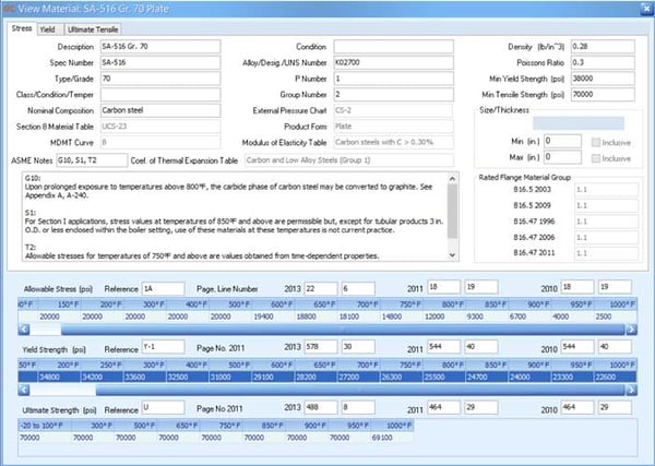
Allowable Stress Example 1: SA-516 Gr 70 Customary for SC8D1
Allowable stress (S, psi) in 2013 is on page 22, line 6
Yield strength (Sy, psi) in 2013 is on page 578, line 30
Ultimate tensile strength (Su, psi) in 2013 is on page 488, line 8.
At 250 degrees S = min(2/3*34200 or 70000/3.5) = 20000 psi
At 650 degrees S = min(2/3*28200 or 70000/3.5) = 18800 psi
At 1000 degrees S is governed by creep data and is 2500 psi; this is less than 2/3*22600 and 69100/3.5
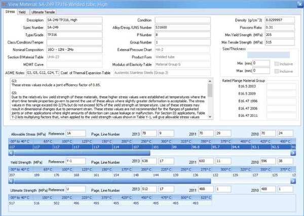
Allowable Stress Example 2: SA-249 TP316, High (90% yield basis) Metric for SC8D1
Allowable stress (S, MPa) in 2013 is on page 78, line 9
Yield strength (Sy, MPa) in 2013 is on page 638, line 17
Ultimate tensile strength (Su, MPa) in 2013 is on page 512, line 17.
At 150 degrees S = min(0.9*0.85*161 or 0.85*516/3.5) = 123.17 MPa, which is higher than the listed allowable of 117 MPa. The allowable at this temperature exceeds the listed SF requirements.
At 250 degrees S = min(0.9*0.85*139 or 0.85*502/3.5) = 106.34 MPa, which is very close to the listed allowable of 107 MPa.
At 375 degrees S = min(0.9*0.85*125 or 0.85*495/3.5) = 95.63 MPa, which is very close to the listed allowable of 95.7 MPa.
Additional Material Properties
Yield Strength
The Yield Strength primarily comes from the Y tables in Section II, Part D. DesignCalcs uses strict matching criteria when linking an allowable stress line from Tables 1A, 1B, and 3 to a yield line in the Y tables, including matching on minimum yield strength, spec, and nominal composition. When a match using these criteria cannot be made, DesignCalcs follows the steps in ASME Section VIII, Division 1, UG-28(c)(2) Step 3, using the material's listed external pressure chart. If a Y table match and the external pressure chart method both fail, the yield will be listed as zero for all temperatures.

Ultimate Strength
Ultimate strength comes from the U tables in Section II, Part D. Similar matching criteria are used to find an ultimate strength match for an allowable stress line.
If a U-table match cannot be used, DesignCalcs employs a conservative method: it assumes the tensile strength governs the allowable stress and solves for it in reverse order. If neither option works, the ultimate strength values will be listed as zero for all temperatures.
Density, Poisson's Ratio, and Other Values
Density and Poisson's Ratio values come directly from Table PRD in Section II, Part D. All materials in DesignCalcs shipping data include both values.
A weight of zero is not a conservative assumption in most cases.30The Modulus of Elasticity (MoE) primarily comes from the TM tables in Section II, Part D. When a clear match cannot be made, DesignCalcs pulls MoE from the external pressure charts (figure form), which include MoE values at various temperatures. If neither option works, MoE values will be zero.
The Mean Coefficient of Thermal Expansion data comes from Section II, Part D TE tables, column B. There is no backup method for this property, and it is currently used in only a few calculations, including sliding saddle slot length and differential thermal expansion in a fixed tube exchanger.
Related Article: 2020 Pressure Vessel & Heat Exchanger Design Guidelines and Resources
Additional Properties Example 1:
This material will back solve for ultimate strength, if necessary, and will get its MoE values from external pressure chart CS-3 as needed.
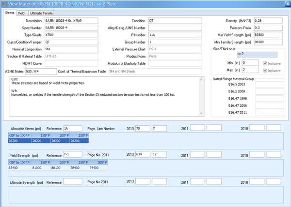
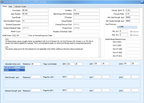
Additional Properties Example 2:
This material will back solve for ultimate strength, if necessary, and will get its MoE and Yield Strength values from external pressure chart NFA-12 as needed.
The designer still needs more flexibility. DesignCalcs provides this with custom materials and manual entry options.
Safety Factor: Historical Changes and How to Handle Them
Earlier editions of ASME Section VIII, Division 1 used a safety factor of 4 on tensile strength instead of 3.5. Until recently, a safety factor of 4 was still required for the design of certain DOT vessels.
DesignCalcs handles this discrepancy in several ways. You can set a vessel safety factor of 4 instead of 3.5. In that case, the allowable stress is calculated using 4 instead of 3.5 in the equations shown above. As a safety measure, DesignCalcs does not allow the calculated allowable stress to exceed the allowable stress from the ASME codebook.
If you want to use your own values for a 4:1 safety factor, or apply a different safety factor on yield, you can either manually input values in the component form for each instance or create a custom material.This approach also works for materials not yet in Section II, Part D but included in a materials code case, such as Code Cases 2402-1 and 2403.
Not all jurisdictions accept code cases, and they may be harder to get accepted by the customer requesting the bid.
More information about custom materials may be found in our help files.

Leave a Comment