When it comes to designing pressure vessels and heat exchangers, having an efficient way to calculate the maximum allowable stresses for Flexible Shell Elements (FSEs) on fixed tubesheets can make a world of difference in an engineer's production time and cost efficiency. Yet, to this day, engineers often use hand calculations to determine these maximum allowables.
And when big money and even bigger safety concerns are on the line, engineers are turning to 2D and 3D modeling software that can accurately calculate stresses on heat exchanger components in minutes.
The following blog gives insight into the ease of using modeling software, like Finglow, that not only simplifies the calculation process for engineers, but provides accurate stress results that are validated in compliance with ASME Section VIII Div 1 and 2 standards. Here's how it works.
Flexible Shell Element Theory from TEMA RCB-8
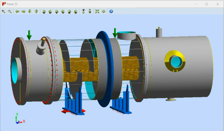
In the latest release of Finglow, which is 2D and 3D modeling software for pressure vessels, heat exchangers and boilers, users can now determine accurate stress calculations on a Flexible Shell Element in minutes.
The software automatically pulls in the methods outlined from TEMA RCB-8 to generate maximum allowable stress points of up to 12 different stress classification lines (SCLs) that exist around a joint.
These SCLs are then automatically calculated using the loading cases defined in Tables UHX-13.4.1 and UHX-13.8.4-1 and the maximum stress is displayed in a report and validated against ASME code.
Stress Classification Lines and ASME Section VIII
As Finglow automatically calculates FSE stresses on a fixed tubesheet, the software simultaneously validates the model against ASME Section VIII Div 1 and Div 2 codes.
The software displays the stress data in a report where users can see the maximum allowable stresses for each component against the stress classification lines as set by ASME Section VIII. The software provides engineers with two options, a simplified analysis or one focused on FSE so that users can view design and operating conditions for a fixed tubesheet in the same report.
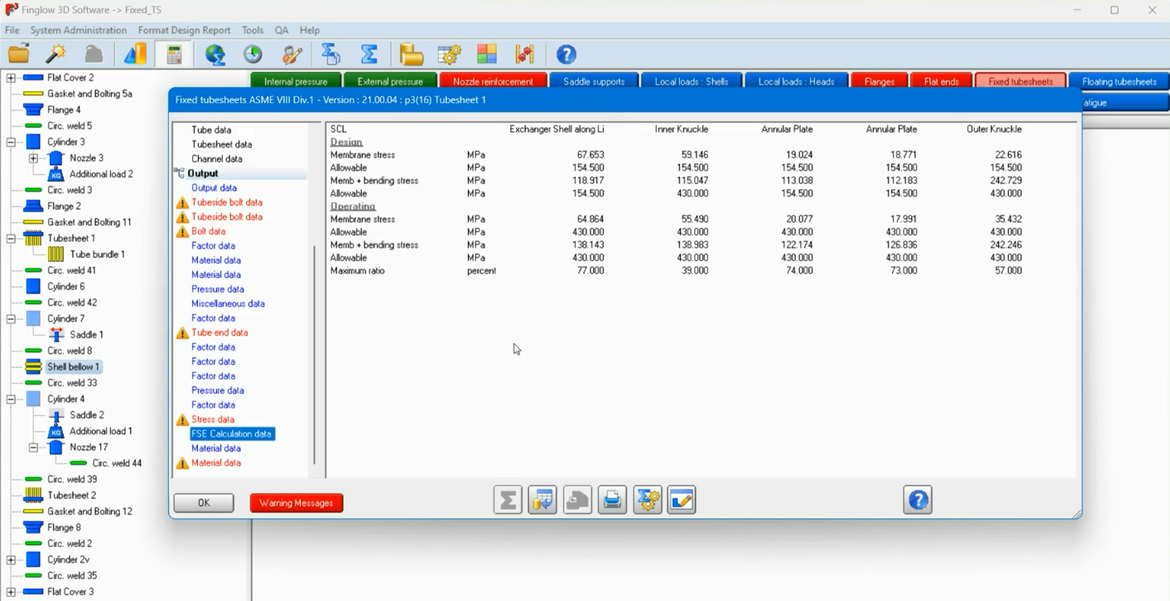
Based on this data, designers can then alter their geometry or submit their project for production along with the downloadable verification results that are aligned with ASME Section VIII Div 1.
The Result: Accurate Stress Data in Minutes
When hand calculations and manually cross checking designs against ASME code is costing more in resources and production time than it should, engineers and designers can turn to 2D and solid modeling software for more accurate stress results that can be produced in minutes.
Finglow combines easy-to-use pressure equipment design tools with automatic ASME Section VIII compliance validation. What's more, Finglow also validates designs against global codes like EN 13445 and PD 5500.
So, if you're needing an easier way to determine your maximum allowable stress results, consider Finglow.
And to see our latest features, visit CEI Software Updates to learn more about what's new with our suite of design and welding software products.

Leave a Comment